ru en
.. ....... НовостиNews - ПоискSearch - ТекстыTexts - ФотоPhotos - КартыMaps - СнаряжениеEquipment - LTLT

Thermometer wires in Fridge4

V.Zavjalov, 2020

wiring DXF(wires)
wiring DXF(wires)

Replacing thermometer and heater wiring in Fridge4. The plan is to convert 3-wire measurements to 4-wire ones (and use new computer-controlled LakeShore resistance bridge), add low-pass filters.

Following wires are to be done:


Wires from device rack to the filter box

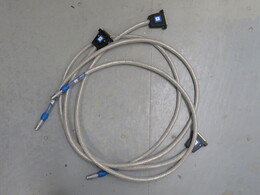
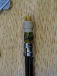
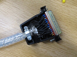
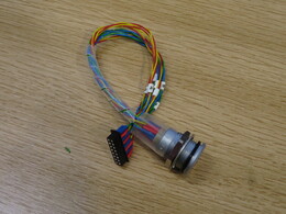
Six cables LEMO FGG.2B.316 to DSUB 25, with same pinout compatable with LakeShore resistance bridge. Each one contains eight RG174 coaxial lines inside the single copper shield. Four cables have length 150 cm, they should go to the resistance bridge scanner mounted on the cryostat flange. Two has length 300(?) cm, they go directly to the device rack.

Copper shield (12x2.3mm): RSN(365-559), plastic cable wrapping (I.D. 10.3mm): RSN(811-7695)

LEMO FGG.2B.316
LEMO FGG.2B.316
DSUB 25
DSUB 25

Filter box

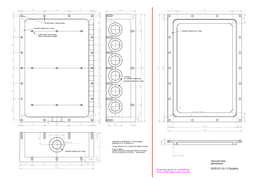
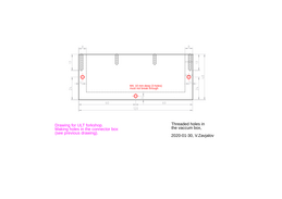
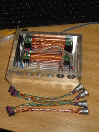
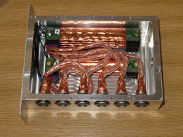
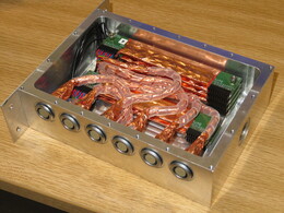
A box with vacuum-tight connectors for 6*16 = 96 wires to be put on the cryostat flange.

Filter box, drawing for workshop DXF(conn_box1)
Drilling additional holes, drawing for workshop DXF(conn_box2)

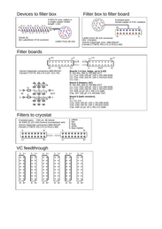
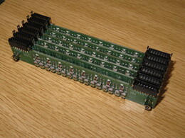
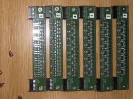
Filter boards was ordered in https://www.multi-circuit-boards.eu (20x130mm, FR4 1.55mm, 76EUR for 12 boards): KiCAD project, Gerber files for ordering.

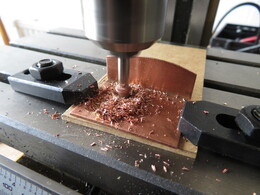
Screw-in KF16 flange and 50 cm metal hose was ordered in https://en.wissel-vakuum.de/. Flange central hole was drilled to 10mm diameter.

filters
filters
Lemo connector for the filter box
Lemo connectors for the filter box, before filling with stycast
filters
filters
filters
filters
filters
filters
installing filters and Lemo connectors in the box

Wires from filter box to the cryostat

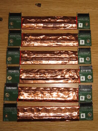
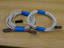
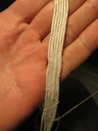
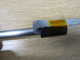
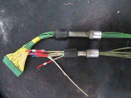
Six cables with 8 twisted pairs in each, Eureka wire, 40swg (0.122mm), length about 200 cm, resistance 86 Ohm/wire. Harwin M80-85016* connectors on both sides (see also here).

constantan twisted pairs
wires
wires

Vacuum can feedthrough

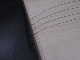
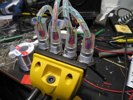
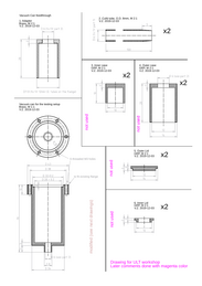
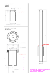
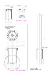
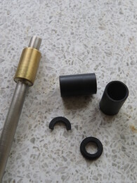
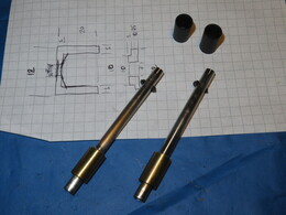
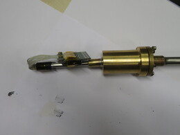
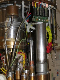
Main feedthrough parts have been done in ULT workshop: 7mm CuNi tube with sharp edge, brass adapter hard-soldered to the tube, small vacuum can for testing. Plastic parts have been done later by me.

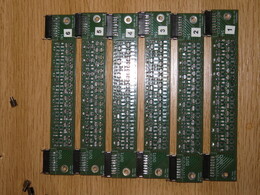
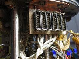
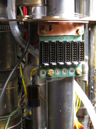
Connector boards was ordered in https://www.multi-circuit-boards.eu (56x44mm, FR4 1.55mm, 73EUR for 12 boards): KiCAD project, Gerber files for ordering.

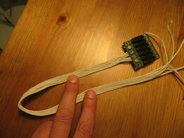
Wires was organized in 6 bundles with 8 twisted pairs each and soldered to the connector boards (Harwin M80-85316 16-pin connectors). Feedthrough was filled with Stycast-1266 and pumped. It would be better to pump Stycast twice: before and after filling.

Parts, 1st drawing for workshop DXF(vc_feedthrough1)
Parts, 2nd drawing for workshop DXF(vc_feedthrough2)
Parts, done by me DXF(vc_feedthrough3)
connecting six cables together
cables with six Harwin connectors
feedthrough parts (see drawings)
after glueing
after glueing
assembled feedthrough
testing setup
testing setup
testing the feedthrough in liquid helium

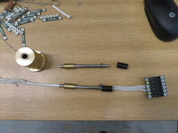
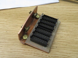
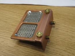
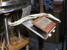
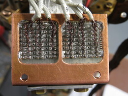
Connector block inside the vacuum can was done using a standard matrix PCB (RSN(391-7232)), soldered to a copper holder.

making windows in the copper holder
old feedthroughs removed from the cryostat
board is temporary fixed to the cryostat for soldering
All wires are soldered
connectors inside the vacuum can
connectors outside the vacuum can

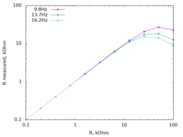
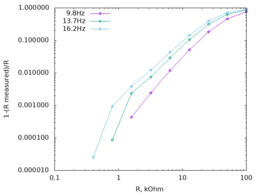
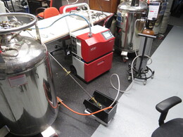
Lines were measured using a decade resistor at room temperature. Resistance bridge excitation 1 $\mu$A, frequency: 9.8, 13.7, 16.2 Hz. Filters works up to resistance 1 k$\Omega$:

measured resistance vs. resistance
error in resistance measurement