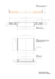
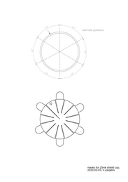
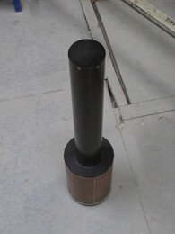
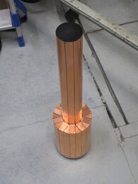
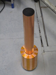
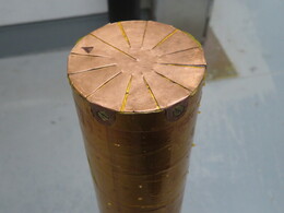
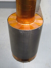
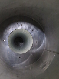
Replacing lower part of the 20mK radiation shield in Fridge4. Original one was done from 2.5"x0.01" stainless steel tube with stainless steel flanges. Shield was covered with copper layer with vertical slits in it. It was replaced by fiberglass tube and GRP flanges, and then covered with stripes of copper tape separated by kapton tape to avoid electrical conductivity around the tube.
Fiberglass tube 65/61 mm was ordered from Excel [1]. Its thermal expansion is 0.143% [2]. Inner part was covered with Stycast-1266 to reduce spreading of glass fibers.
[1]Universal Glassfibre tube 65/61 mm, L100 cm, Excel (~22EUR)
https://www.exelwebstore.com/catalog/product/view/id/979/s/universaltm-glassfibre-tube-65-61-mm-l100-cm.
[2]http://slazav.xyz/notes/2018_th_exp.htm
We have a brass (or stainless steel) thermal shield, a tube with radius $r$, length $L$ and wall thickness $x$. Lower end of the shield (of length $l$) is located in magnetic field parallel to the tube axis which is changing with rate $dB/dt$. Upper end is thermalized to temperature $T_0$. What will be temperature $T$ of the lower end?
Electromotive force (in SI units) is \begin{equation} |E| = \frac{d\Phi}{dt} = \pi r^2 \frac{dB}{dt}, \end{equation} and heating produced by it is \begin{equation} \dot Q = E^2/R = \pi r^2 \frac{dB}{dt} \frac{lx\sigma}{2\pi r}, \end{equation} where $R$ is resistance around the tube, and $\sigma$ is electric conductivity of tube material.
This heat goes from the lower end to upper one: \begin{equation} \dot Q = K 2\pi r x \frac{dT}{dL}, \end{equation} where $K$ is thermal conductivity which is connected to electrical conductivity by Wiedemann-Franz law: $K = T \sigma \lambda$, $\lambda=2.44\cdot10^{-8}$~[W$\Omega$K$^{-2}$].
By integrating this over length $L$, we have \begin{equation} \dot Q = (T^2-T_0^2) \sigma \lambda \pi rx/L. \label{eq_q3} \end{equation} Result is: \begin{equation} T^2-T_0^2 = \left(\frac{dB}{dt}\right)^2 \frac{l L r^2}{2\lambda}. \end{equation} It does not depend on material and wall thickness.
Now let's cover the shield with copper of thickness $y$ with a vertical slit of width $d \ll R$. Resistance around the tube will change to \begin{equation} R = \frac{2\pi r}{l(x\sigma + y\sigma_{\mbox{cu}})} + \frac{d}{lx\sigma}, \end{equation} and the thermal conductivity formula \eqref{eq_q3} will be \begin{equation} \dot Q = (T^2-T_0^2) (x\sigma + y\sigma_{\mbox{cu}}) \lambda \pi r/L \end{equation} (if copper resistance does not change along the shield)
By putting some reasonable values: \begin{eqnarray} dB/dt &=& 10^{-3} \mbox{ T/s}\\\nonumber l &=& 0.2 \mbox{ m}\\\nonumber L &=& 0.4 \mbox{ m}\\\nonumber r &=& 0.063 \mbox{ m}\\\nonumber \sigma &=& 1.5\cdot 10^{7} \mbox{ S/m (brass)}\\\nonumber && 1.4\cdot 10^{6} \mbox{ S/m (st.st. 304)}\\\nonumber && 1.8\cdot 10^{9} \mbox{ S/m (copper, RRR=30)}\\\nonumber \lambda &=& 2.44\cdot10^{-8} \mbox{ W}\Omega\mbox{K}^{-2} \end{eqnarray} we have
| $E$, $\mu$V | $R$, $\mu\Omega$ | $\dot Q$, $\mu$W | $T$, mK | |
| 0.254 mm wall, st.st., 0.05mm copper layer with 4mm slits | 12.47 | 78.15 | 1.990 | 47.16 |
| same, no copper layer | 12.47 | 5566. | 0.028 | 83.11 |
| brass, 1mm thick | 12.47 | 131.9 | 1.178 | 83.11 |
Heating of the shield by radiation from the outer shield ($T_o\approx 1$ K): $\dot Q_r = 5.67\cdot10^{-8} 2\pi rl T_o^4 \approx 9$ nW.