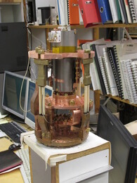
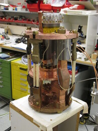
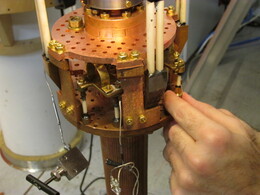
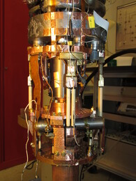
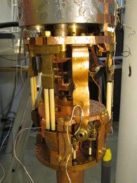
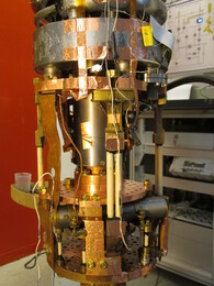
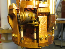
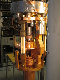
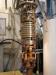
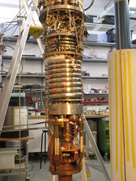
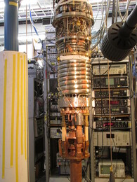
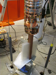
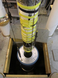
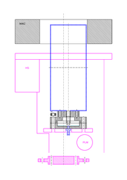
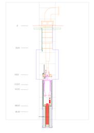
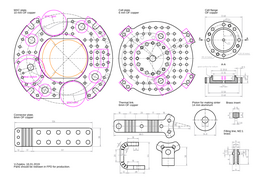
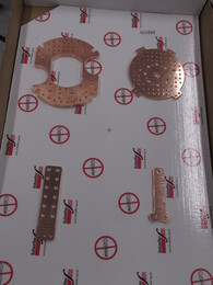
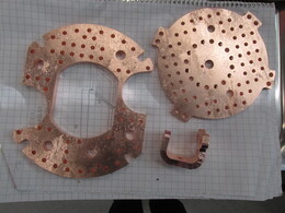
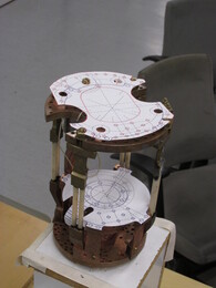
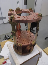
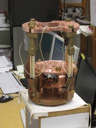
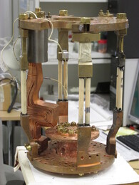
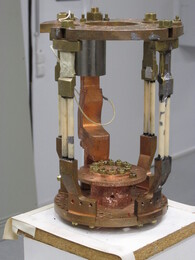
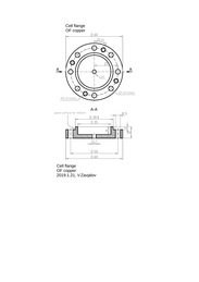
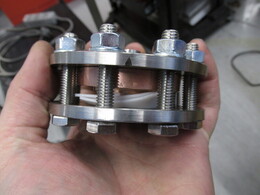
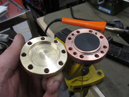
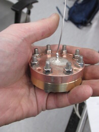
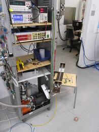
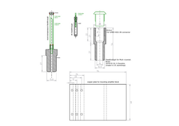
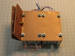
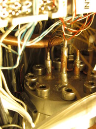
Cell is installed to Muki cryostat using holders for the previous cell. The plate for the cell, the thermal link to the nuclear stage, and the new mixing chamber plate (with larger hole) were ordered in SchaefferAG. Price was 295 EUR for two OF copper plates (10 and 6 mm thick) and two small 6 mm pieces (a thermal link and a connector plate which was not used in this setup). The upper flange was designed in such a way that it fits into LTL furnace. FPD files.
Plates were annealed at 900$^\circ$ for 24 hours at about $0.1$ mbar of air. Pressure of air was too large, plates were oxidized (red color). Then they were annealed at 950$^\circ$ for about 4 hours without air (almost no effect) and then at 950$^\circ$ for about 56 hours with $5\cdot10^{-4}$ mbar of air. During the last annealing oxide was fully removed.
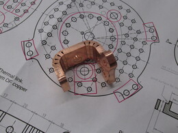
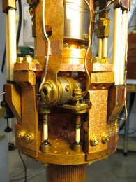
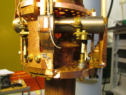
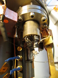
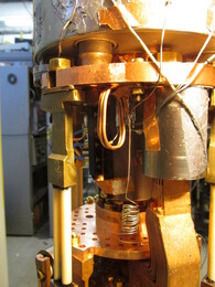
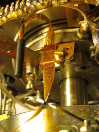
A very good heat switch, done by A.Sebedash for Muki cryostat (TODO: find paper, parameters). During installation of the new cell one ceramic support was broken and replaced. It looks like performance of the heat switch become worse after this.
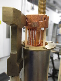
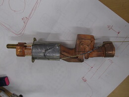
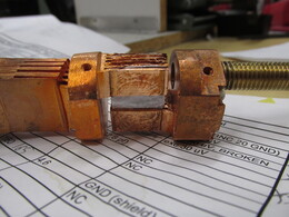
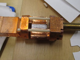
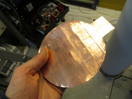
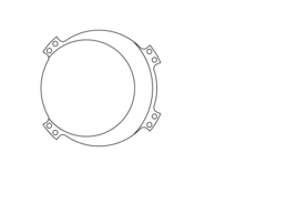
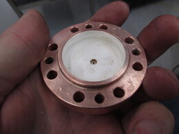
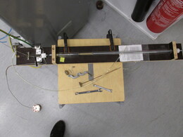
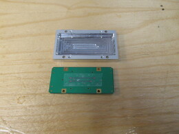
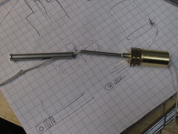
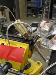
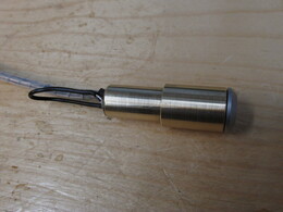
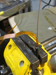
Cell bottom flange was made in LTL workshop. It was annealed at 900 degrees for 4 hours with $5\cdot10^{-2}$ mbar of air. A brass flange for filling tube was hard-soldered. Mistake 1: wrong torch setting, too cold flame. Mistake 2: fixing the flange in a clamp during soldering, deformation. Mistake 3: trying to remove oxide with heating (with brass part covered with a copper cap). Then it was resoldered and cleaned.
Silver plating bath:
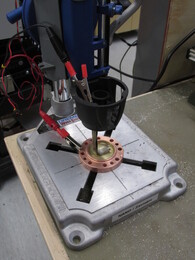
Current for the bath: 2 mA/cm$^2$ (Cu+, Ag-), 1 $\mu$m/8min. We did the silver plating of the flange about 40 minutes at twice smaller current.
Original recepy says that powder should be compressed with pressure 500-1500 kg/cm^2 and baked at 150 C for 1h. 1g of silver powder should give area 1-2 m^2.
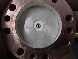
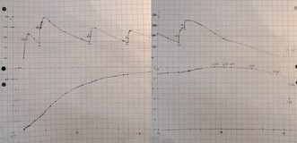
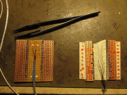
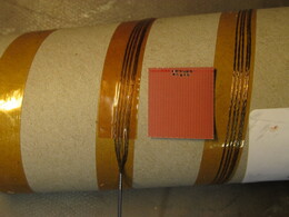
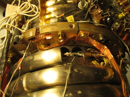
Silver sinter: using 2.5g of presintered powder from Matti Männinen, pressing with LTL oil press at full force (check the force!) Clamping in a stainless steel clamp with 2mm of teflon. Baking at large furnace at 150(?) C for about 30 min (see plot below). Temperature was controlled using a thermocouple attached to the flange. The furnace is too big and slow, annealing process was too long, measured sinter area (1.68 m$^2$) was smaller than expected.
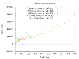
Sinter area was measured using BET method: cell filled with N$_2$ gas was cooled to 77 K. Amount of condenced gas was measured using values of cold and hot volumes (measured with a piston) and pressure difference at constant volume (or volume difference at constant pressure) as a function of cold-temperature pressure.
In BET model [1] amount of adsorbed gas depends on pressure $P$ in the following way: $$ n_{\mbox{ads}} = n_{\mbox{site}} \frac{CP}{P-P_0} \frac{1}{1+(C-1) P/P_0} $$ where $n_{\mbox{site}}$ is amount of "adsorption sites", $6.1728\cdot10^{18}$ molecules per m$^2$, $P_0$ is condensation pressure (1 bar for nitrogen at 77 K) and $C$ is the model parameter. At low pressure amount of adsorbed gas grows linearly with pressure, until first atomic layer is filled. Then slope decreases, and then start growing again to go to infinity at $P_0$ (condensation of the gas).
It was very important to have small enough volume of the system. Measurements with total volume about 50 cm$^3$ fail, we managed to get a good result only after decreasing the volume to about 5 cm$^3$.
Measurement gave us $C=27.15$, and $1.689\cdot10^{-5}$ mol which corresponds to sinter area 1.69 m$^2$. For the cell volume 9.84 cm$^3$ (measured) it gives thermalization time constant above $T_c$ of about 1000 seconds.
[1] Adsorption of Gases in Multimolecular Layers
Stephen Brunauer, P. H. Emmett, and Edward Teller
Journal of the American Chemical Society 1938, 60, 2, 309-319 (1938)
https://pubs.acs.org/doi/pdf/10.1021/ja01269a023
[2] Physisorption of gases, with special reference to the evaluation of surface area and pore size distribution (IUPAC Technical Report)
Matthias Thommes, Katsumi Kaneko, Alexander V. Neimark, James P. Olivier, Francisco Rodriguez-Reinoso, Jean Rouquerol, Kenneth S.W. Sing
Pure and Applied Chemistry 87, 1052 (2015)
https://www.degruyter.com/view/journals/pac/87/9-10/article-p1051.xml
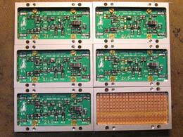
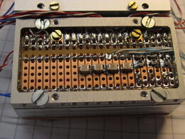
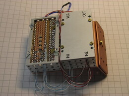
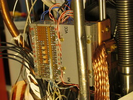
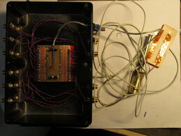
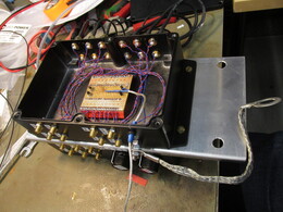
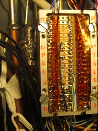
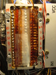
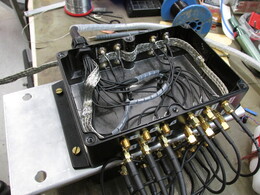
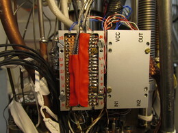
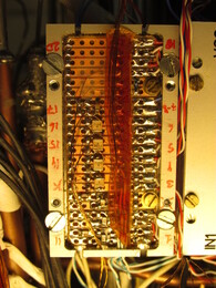
4K amplifier box: 5 amplifiers (v21.1 .. v21.5) without cascodes, for 3 NMR channels and 2 forks. A connection box which also contains some smd components: 10pF inpit capacitors for NMR excitation, 1nF+ tank cirquit capacitors, 100k resistors for Q-value limiting, 1k resistors for NMR compensation (forms 1:20 attenuator with 50R compensation input) 200pF high-Q capacitors for fork inputs and outputs.
TODO: text about amplifiers with kicad project and box drawings.
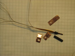
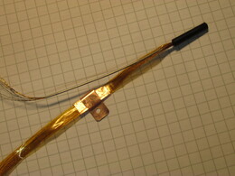
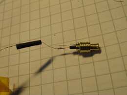
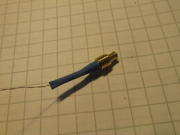
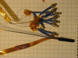
Signal wires (forks, NMR), 4K -- room (first version): 20 twisted pairs (0.07mm NbTi in Cu matrix, ~10 Ohm/m) in a single fabrique sleeve. Feedthrough with CuNi tubes and Stycast 1266. Cu shielding outside the cryostat. Large crosstalk between pairs!
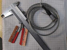
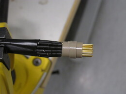
Signal wires (forks, NMR), 4K -- room (second version): Manganin wire: R = 12.4 for 130cm wire. CuNi shield: R = 7.6 for 130cm wire (GVLZ037 shield by GVL cryoengineering). 3 Twisted pair: C = 152.8pF / 135cm. 8 Coaxial w/o teflon: C = 161.6pF / 135cm. 5 Coaxial with teflon: C = 96.0pF / 135cm. Lemo connector on the room-temperature flange. RG174 coax cables to the connector box.
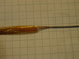
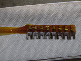
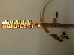
Signal wires (forks, NMR), 1mK -- 4K: Ten 0.1mm Neomax twisted pairs, glued on kapton tape. ~45 Ohm/wire. 4K feedthrough with thin CuNi tube, GRP form and 1266 Stycast. Thermalization with Cu tape and Cu clamps on 1K and 50mK levels. Wires picks up huge 50 Hz signal. Wires were shielded with copper tape on every thermal stage and aluminum tape below 50mK plate, this helps. In the dewar in should be better.
Magnet wires
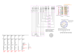
All experiment wires: